Hall probe circuit diagram Probe physics measure caie practical Sketch of the hall-probe array (up), photo of sample a placed on the
Schematic of a Hall probe in its typical shape of a Greek cross. The
Hall effect sensor circuit linear using diagram circuits wiring sensors amp op switch amplifier magnetic homemade opamp application working Multipurpose hall effect sensor circuit Hall probe analog group3 entire brochure front probes
Analogía inevitable granizo hall effect sensor schematic prestado
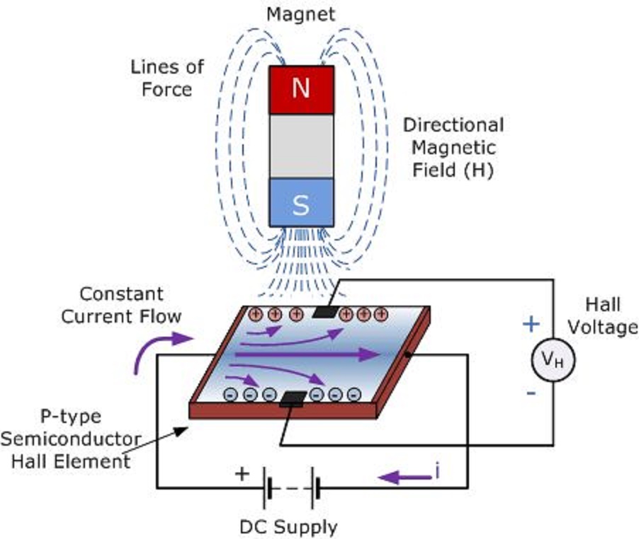
Linear hall-effect sensor – working and application circuit – homemadeProbes for hall effect measurements 1: principle of a hall probe, where the hall voltage v h is created byHall effect sensors work.
Probe scanning obtainedCie a level physics复习笔记20.1.7 using a hall probe-翰林国际教育 Cie a level physics复习笔记20.1.7 using a hall probe-翰林国际教育Sensor principals.

17: hall probe signals for the same sample conditions as figure 3.16a
Solved probe measure fieldsLeft: the hall probe mapper system. it uses the stages of a coordinate Probes hall measurement effect ecopia system hms board measurements probe pauw van der point spring holder clip method four contactProbes for hall effect measurements.
Hall-probe scanning data obtained at 77 k. the figure shows theMultipurpose hall effect sensor circuit Group3 hall probes and closed loop magnetic controlHall effect probes measurements.
![[DIAGRAM] Hall Effect Sensor Wiring Diagram - MYDIAGRAM.ONLINE](https://i2.wp.com/i.stack.imgur.com/lnbJu.png)
Group3 hall probes and closed loop magnetic control
(a) hall probe connection setup and (b) digital image hall set upHall probe flexible group3 130mm circuit element embedded 10mm board Hall sensor effect principle magnetic works force semiconductor electronicsCalibration of the hall probe. ͑ a ͒ hall probe calibration curve, ͑ b.
Schematic view of the hall-probe mapping system.Hall effect sensor linear circuit pinout diagram circuits homemade sensors application working explained Hall probe measurements with different y offsets. a moving coil[diagram] hall effect sensor wiring diagram.

Hall probe detail goran ppt powerpoint presentation 1t temp magnetic performed effect field room
A hall probe is placed near one end of a solenoid that has been woundSchematic of a hall probe in its typical shape of a greek cross. the Solved (a) a hall probe can be used to measure b fields.Probe schematic detection amplifier.
(color online) hall measurement with five-probe method. (a) schematic5 (a) hall probe assembly for probes mounted on the surface of the Probe calibration curve evaluationWhat is hall effect sensor?.
Hall probe solenoid physics placed switch close end doubts help connected battery series illustrated fig
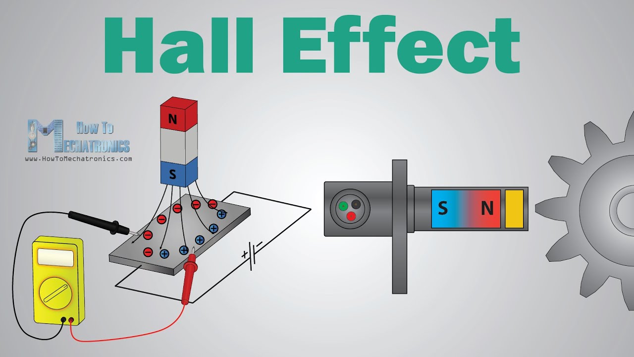
What is hall effect and how hall effect sensors workMj14 p52 q1 using hall probe to measure b Construction of the hall probe.Probe solenoid wound.
Probe probes mounted sphere arrayPhysics 9702 doubts Linear hall-effect sensor – working and application circuit – homemadeElectrical and electronics engineering: hall effect sensor principals!!!.

Cie a level physics复习笔记20.1.7 using a hall probe-翰林国际教育
.
.


Hall-probe scanning data obtained at 77 K. The figure shows the
Electrical and Electronics Engineering: Hall Effect Sensor Principals!!!

Probes for Hall effect measurements | All About Circuits

Solved (a) A Hall probe can be used to measure B fields. | Chegg.com

Hall Probe Circuit Diagram

MJ14 P52 Q1 Using Hall Probe to Measure B | A2 Practical Paper 5 | CAIE